System Introduction
The VYCON Direct Connect VDC and VDC XE are flywheel energy storage systems consisting of two major subsystems:
? The flywheel module, which includes the high strength steel hub (flywheel rotor), high speed permanent magnet motor/generator and a five axis active magnetic bearing system.
? A three-phase bidirectional Insulated Gate Bipolar Transistor (IGBT) bridge (AC/DC converter) used for both motoring and generation.
The output and input to the VDC are through a DC bus connected to the converter. The converter creates a sine wave from the DC bus to spin the flywheel during motoring and converts the varying sinusoidal frequency from the flywheel into DC voltage during generation (i.e., energy discharge). Energy is removed from the flywheel rotor by the generator. In the VDC, the energy is 3000 kW-sec at 100kW and in the VDC XE the maximum energy is 4000 kW-sec at 100kW.
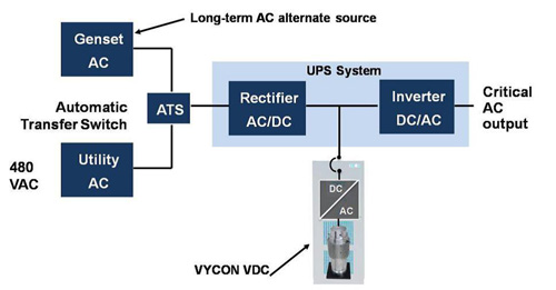
Figure 1 shows a simplified block diagram of an Uninterruptible Power Supply (UPS) that uses the VDC for continuous power conditioning and power source backup. In the event of a loss of line input from the utility grid, the VDC immediately goes into discharge mode, maintaining the DC bus of the UPS to support the critical loads with no interruption. Upon restoration of input power by a generator set (genset) or recovery of the utility, the VDC recharges to full operating energy and awaits the next event. The VDC can be used in a variety of applications including backup power during genset ride-through, “battery hardening,” load-leveling for standby gas turbines and continuous power conditioning.
The VDC is designed to work with a UPS system and connects into the same DC bus for both charging (motoring) and discharging (generating) power. A 4-line LCD display or an optional Graphical User Interface (GUI) with remote communication capabilities provide convenient control and monitoring of performance parameters.
4-Line LCD Display and Optional Touchscreen Graphical User Interface
The VDC may be commanded from the standard 4-line LCD display or by an optional Touchscreen Graphical User Interface which has a touchscreen display. The touchscreen incorporates a system status window, navigation buttons and system functionality options that allow the user to monitor the VDC.
Power Conversion Module (also referred to as Power Stack or Bi-Directional Converter)
The charging—motoring, as well as discharging (generating)—of the flywheel energy storage system is accomplished through control of semiconductor switches incorporated into the flywheel power conversion module. Since the flywheel operates in a vacuum, mitigation of the current harmonics present in the flywheel stator windings is accomplished by using fast switching IGBTs. The IGBTs are rapidly turned on and off to closely approximate a sine wave through the use of Pulse Width Modulation (PWM). The correct waveform is critical in reducing harmonics, along with controlling current ripple.
The VDC features a pre-charge cycle of the power conversion module capacitors. This cycle allows connection of an electrically “cold” system to the “hot” DC bus of the UPS by ensuring that the initial high inrush current is limited through a pre-charge resistor.
Vacuum Pump
A rotary vane vacuum pump is used to maintain the vacuum level in the flywheel at the required level during operation. The pump minimizes the windage losses created by the high speed rotor and increases the overall electrical efficiency of the flywheel.
Magnetic Bearing Controller (MBC)
The magnetic bearing controller provides levitation control of the flywheel hub (rotor) and contains a digital controller, a sensor demodulator and current amplifiers. The MBC monitors and controls the position of the flywheel rotor via a five-axis active magnetic bearing system. Rotor position signals are fed to the control module of the MBC, which runs a digital filter compensation program to produce a command signal for each current amplifier. The current amplifiers provide the drive current to the actuators (controllers) of each axis, thereby applying the forces on the rotor maintaining the desired flywheel rotor position.
Flywheel Controller
The flywheel controller is the intelligence of the flywheel system and contains a digital controller that monitors and controls the various subsystems within the VDC.
Functions of the flywheel system controller include charging (motoring) and discharging (generating) of the flywheel, controlling and monitoring of the subsystem components and handling system alarms, faults and shutdown.
Emergency Power Off
The emergency power off feature on the front of the VDC allows the operator to disable the system in the event of an emergency. The emergency power off may also be activated remotely via a normally open dry contact.
Flywheel
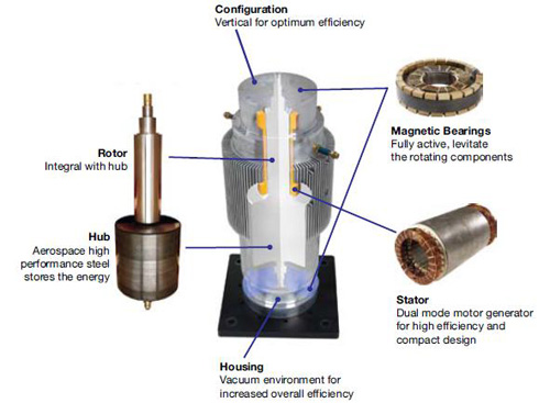
The core of the VDC is the flywheel, which stores the kinetic energy and is designed for high-power, short-discharge UPS applications. Figure 3 illustrates a cross-section of the flywheel and associated hardware. A description of the key flywheel components is provided below.
Flywheel Components
The key flywheel components are the housing, motor/generator, flywheel rotor and magnetic bearings.
※Housing
The aluminum flywheel housing aligns and supports the bearings and the stator. Alignment is critical to prevent contact between the rotor and other components. Vacuum sealed connectors are used for the high-power electrical leads. Vacuum feed-throughs are used for the magnetic bearing electrical power, speed sensor and temperature sensor connections. Additional vacuum seals are located at the top and bottom of the flywheel for access during manufacturing.
※Motor/Generator
The motor/generator consists of a unique stator and rotor assembly designed to operate effectively in a vacuum environment. The stator assembly is designed to minimize rotor losses that are difficult to remove in a vacuum environment. Stator cooling is accomplished via conductive transfer of heat to the flywheel housing. The permanent magnet of the motor/generator is integrated with the flywheel rotor and retained by a high-strength non-magnetic alloy. The magnet retainer also functions as the main stiffness member for the entire flywheel rotor assembly.
※Flywheel Rotor
The flywheel stores kinetic energy in the form of a rotating mass. The rotor hub (flywheel rotor) is manufactured from a high-strength grade steel. At full operating speed, the stress levels in the rotor provide an ample safety factor, meeting stringent criteria for design life, flaw tolerance and cyclic life for UPS applications.
※Magnetic Bearings
Magnetic bearings are used for rotor support. The bearings fully levitate and suspend the rotor in a magnetic field, responding to both static and dynamic forces. The magnetic bearings provide radial and axial support. To minimize bearing power requirements and losses, the flywheel is vertically oriented, requiring only the axial bearing axis to support the full rotor weight.
Magnetic bearings possess unique advantages in operation and longevity of flywheel systems. These advantages include extremely long life with no maintenance, high reliability, tolerance to unbalance, minimum rotor losses and low power consumption.